If you’re into film photography, you probably have some mechanical shutter cameras. As these cameras age the mechanisms get sticky and this can affect shutter speeds. It’s good to know if your shutter speeds are accurate and this device is very useful to test them. Once you know how far off from correct your shutter speed is, you can either repair/adjust the mechanism or compensate with aperture settings.
It gives all the detail on parts required along with breadboard layout, schematic and code, al of which you can also find below.
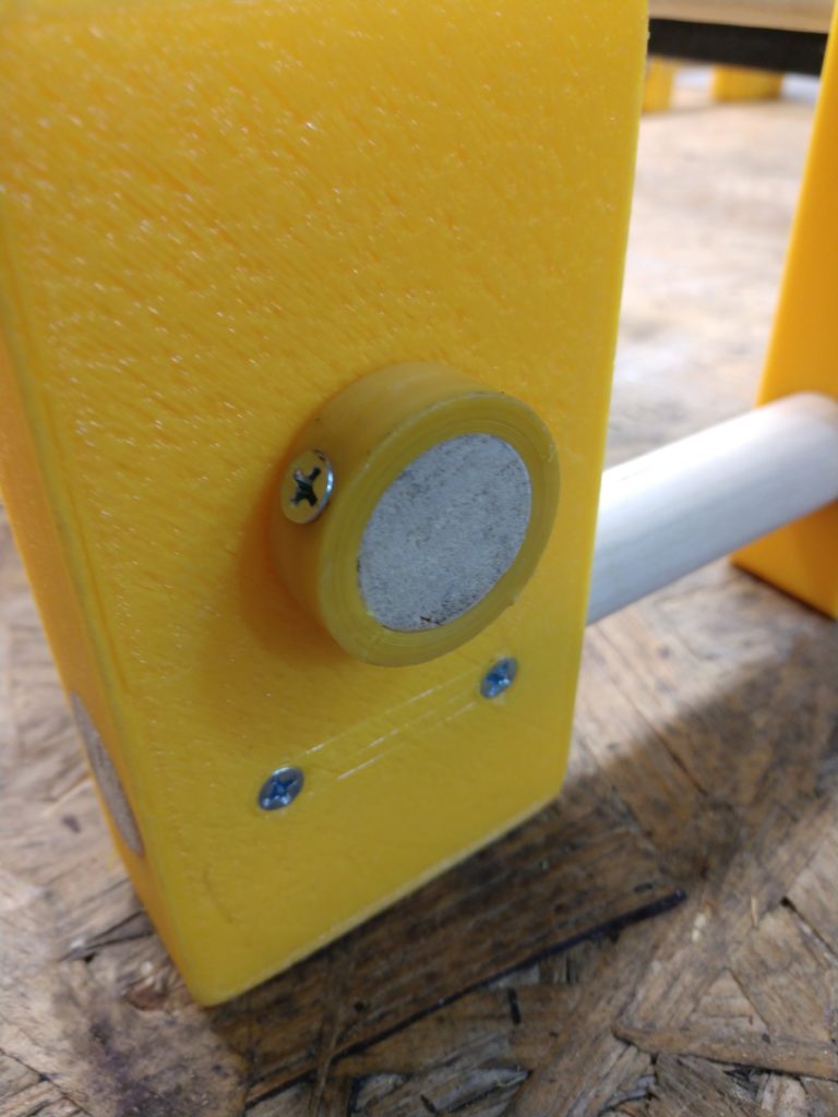
It’s a fairly simple build and it works well. The video posted below is in two parts. The first goes over p breadboarding and testing the project and the second covers building a 3D printed enclosure.
Parts: 1 – 10K ohm resistor 1 – Photo transistor SFH309-4 Mouser part #720-SFH309-4 1 – Arduino Micro or equivalent. 1 – bright white LED or a flashlight. 1 – 0.96″ OLED Display 128 x 64 SSD1306 I2C available from Amazon You’ll need to download the latest version of “Adafruit SSD1306” OLED library for your code.
I own a 2003 EuroVan. It’s a great van but it has one major weak point. The 01M or 01P automatic transmission. This transmission is known to fail around 190K miles. Symptoms are hard shifting, a clunk when engaging reverse, not shifting out of 1st gear, sluggish shifting and slipping or not moving at all when hot. It does have a factory oil to water cooler but it’s really inadequate. Adding an auxiliary oil cooler helps but they still eventually fail. A rebuilt unit currently will cost around $6,000 – $7,000 to buy and install.
About 2 years ago, my transmission failed. It went CLUNK and felt like it was in two gears at once with crunchy sounds. Not good. Fortunately it happened at the shop I used to operate so I just parked it.
An alternative is to install a 02G AFL 5 speed manual transmission. These can be purchased with all the extras you will need from Quality German Auto Parts in Victorville CA. There is currently a waiting list but when they are available they cost about the same as a rebuilt automatic. I bought one and it came with everything I needed to do the conversion.
There are big advantages to switching to a manual. No more worries about the automatic failing, better fuel mileage and much better performance. Mine van now does 0 – 60 mph in 10 seconds! Not bad for a EuroVan.
There are some issues that come up though. This thread on the Samba forum goes into detail, but suffice to say that the Check Engine Light (CEL) will stay on because the transmission control module (TCM) no longer receives signals from the missing transmission. It will log up to 14 codes for missing signals. If you remove the TCM you will get ABS and stability control warning lights and your ABS will not function. In several states a CEL means you can’t pass yearly inspection and you can’t register the vehicle.
UPDATE AS OF MARCH 2023. NEW BETTER VERSION.
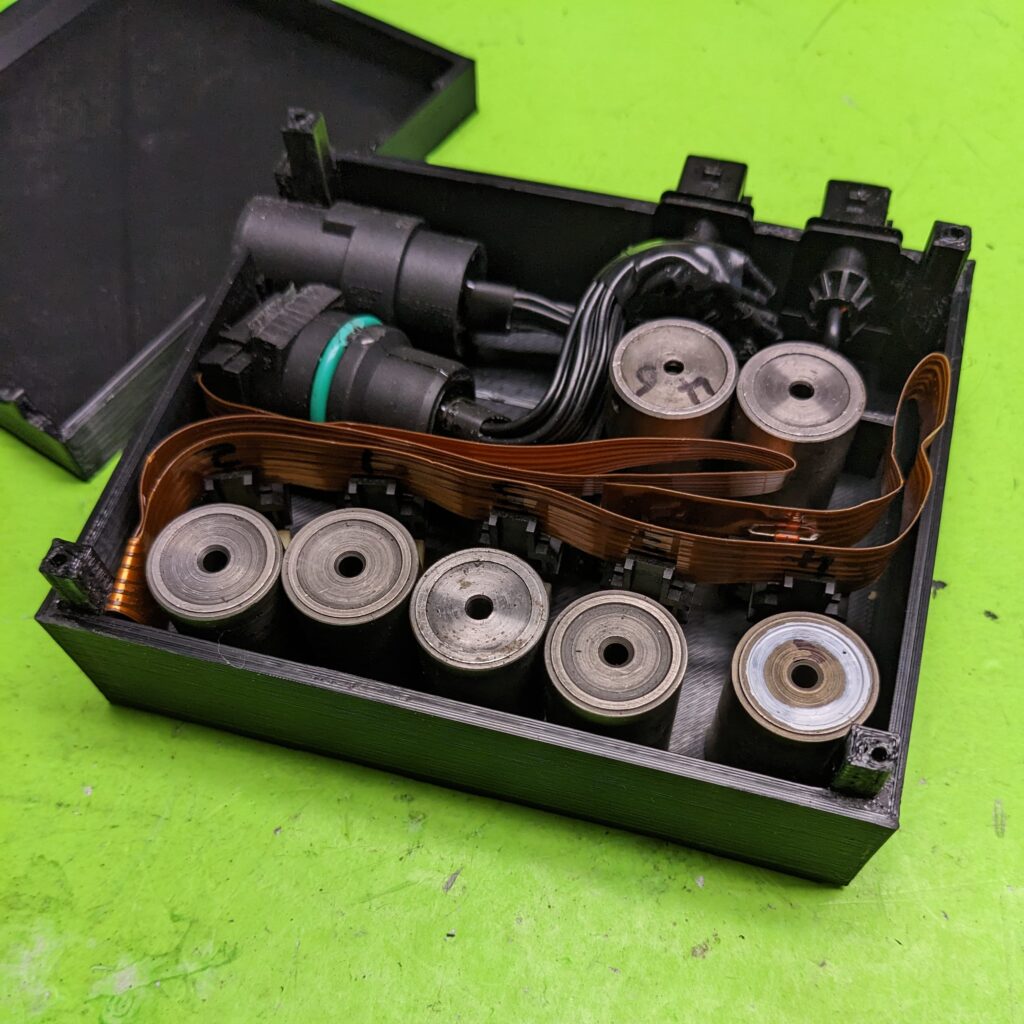
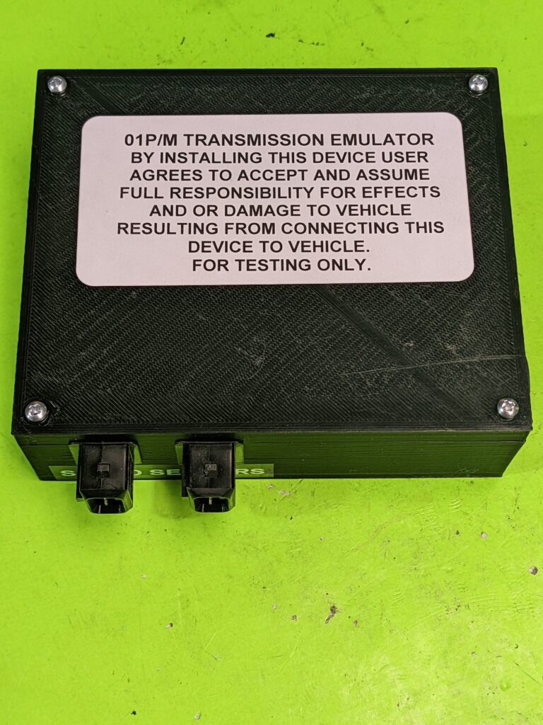
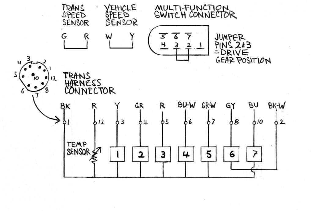
After much research and tinkering I’ve come up with a solution in the form of a hardware hack. First of all, you need to leave the TCM and it’s wire harness that used to connect to the transmission installed in the van. The wire harness is needed to connect to the device I’ve come up with. I call this device the Transmission Emulator. It’s made up of the same solenoids and ribbon cable that is inside the transmission. The external connectors are for the two speed sensors and the valve body harness. There is also a plug that connects to the multi-function switch socket that replaces the switch. The speed sensor connectors are simply jumper wired. When installed the TCU detects the solenoids, the speed sensors are there and the multi-function switch is in D position. So as far as the TCM is concerned, the vehicle is turned on, not moving and in drive. There is no longer a reason to request a CEL from the engine control module.
Installation is very straight forward. Plug the three connectors into the emulator and install the jumper plug into the multi-function switch. Connect a code scanner, turn on ignition switch, clear all codes and no more check engine light!
Below are some pictures and wiring diagrams of the emulator. If you are handy with hardware hacking you can build one yourself OR you can send me a donation of $265 shipping included and I’ll send you a unit like the one pictured, complete with instructions, ready to plug in.
My wife Lisa and I recently got into weaving and wanted a larger heddle loom than the small one I bought her for Christmas. After a search on Thingiverse I found this excellent design from user ten16. It utilizes 3D printed parts and wood dowels in it’s construction and it can be built as wide and long as you wish. There were no instructions for assembly (other than a few pictures) so I thought it would make for a good step by step project video on my YouTube channel.
Rigid Heddle Loom
Here is a list of dowel sizes and lengths to build a 16″ x 30″ loom like the one in my video:
I used PLA for the heddles printed at 205C with a bed temperature of 70C and a 50% infill in draft quality. All other pieces were printed with PETG at 235C, bed 70C, 20% infill except for the retaining rings and winding braces which were printed at 100% infill for extra strength.